- 您现在的位置:买卖IC网 > Sheet目录3875 > PIC16F628A-I/P (Microchip Technology)IC MCU FLASH 2KX14 EEPROM 18DIP
2009 Microchip Technology Inc.
DS40044G-page 139
PIC16F627A/628A/648A
17.3
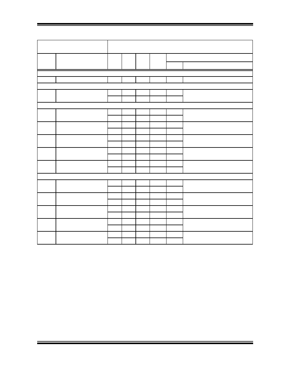
DC Characteristics: PIC16F627A/628A/648A (Extended)
DC CHARACTERISTICS
Standard Operating Conditions (unless otherwise stated)
Operating temperature
-40
°C ≤ Ta ≤ +125°C for extended
Param
No.
Device Characteristics
Min
Typ
Max
Units
Conditions
VDD
Note
Supply Voltage (VDD)
D001
—
3.0
—
5.5
V
—
Power-down Base Current (IPD)
D020E
——
0.01
4
μA
3.0
WDT, BOR, Comparators, VREF and
T1OSC: disabled
—0.02
8
μA5.0
Peripheral Module Current (
ΔIMOD)(1)
D021E
——
2
9
μA3.0
WDT Current
—9
20
μA5.0
D022E
—
29
52
μA
4.5
BOR Current
—30
55
μA5.0
D023E
—
22
37
μA
3.0
Comparator Current
(Both comparators enabled)
—44
68
μA5.0
D024E
—
50
75
μA3.0
VREF Current
—83
110
μA5.0
D025E
——
1.3
4
μA
3.0
T1OSC Current
—1.8
6
μA5.0
Supply Current (IDD)
D010E
—
15
28
μA3.0
FOSC = 32 kHz
LP Oscillator Mode
—28
54
μA5.0
D011E
——
175
340
μA3.0
FOSC = 1 MHz
XT Oscillator Mode
—320
520
μA5.0
D012E
——
450
650
μA3.0
FOSC = 4 MHz
XT Oscillator Mode
—
0.710
1.1
mA
5.0
D012AE
——
565
785
μA3.0
FOSC = 4 MHz
INTOSC
—
0.895
1.3
mA
5.0
D013E
—
2.5
2.9
mA
4.5
FOSC = 20 MHz
HS Oscillator Mode
—
2.75
3.5
mA
5.0
Note 1:
The “
Δ” current is the additional current consumed when this peripheral is enabled. This current should be
added to the base IDD or IPD measurement. Max values should be used when calculating total current
consumption.
发布紧急采购,3分钟左右您将得到回复。
相关PDF资料
PIC18F24K22-I/SO
IC PIC MCU 16KB FLASH 28SOIC
PIC18F23K22-I/SP
IC PIC MCU 8KB FLASH 28SPDIP
PIC18LF23K22-I/SP
IC PIC MCU 8KB FLASH 28SPDIP
PIC24F08KA102-I/SS
IC PIC MCU FLASH 8K 28-SSOP
PIC16C58B-20/SO
IC MCU OTP 2KX12 18SOIC
PIC12C672-04/SM
IC MCU OTP 2KX14 A/D 8-SOIJ
PIC18F25K20-E/SS
IC PIC MCU FLASH 16KX16 28-SSOP
PIC18F25J10T-I/SO
IC PIC MCU FLASH 16KX16 28SOIC
相关代理商/技术参数
PIC16F628A-I/P
制造商:Microchip Technology Inc 功能描述:IC 8BIT FLASH MCU 16F628 DIP18
PIC16F628A-I/SO
功能描述:8位微控制器 -MCU 3.5KB 224 RAM 16 I/O RoHS:否 制造商:Silicon Labs 核心:8051 处理器系列:C8051F39x 数据总线宽度:8 bit 最大时钟频率:50 MHz 程序存储器大小:16 KB 数据 RAM 大小:1 KB 片上 ADC:Yes 工作电源电压:1.8 V to 3.6 V 工作温度范围:- 40 C to + 105 C 封装 / 箱体:QFN-20 安装风格:SMD/SMT
PIC16F628A-I/SO
制造商:Microchip Technology Inc 功能描述:8BIT FLASH MCU SMD 16F628 SOIC18
PIC16F628A-I/SOG
制造商:Microchip Technology 功能描述:MCU 8-Bit PIC16 PIC RISC 3.5KB Flash 3.3V/5V 18-Pin SOIC W Tube
PIC16F628A-I/SS
功能描述:8位微控制器 -MCU 3.5KB 224 RAM 16 I/O RoHS:否 制造商:Silicon Labs 核心:8051 处理器系列:C8051F39x 数据总线宽度:8 bit 最大时钟频率:50 MHz 程序存储器大小:16 KB 数据 RAM 大小:1 KB 片上 ADC:Yes 工作电源电压:1.8 V to 3.6 V 工作温度范围:- 40 C to + 105 C 封装 / 箱体:QFN-20 安装风格:SMD/SMT
PIC16F628A-I/SS
制造商:Microchip Technology Inc 功能描述:8BIT FLASH MCU SMD 16F628 SSOP20
PIC16F628AT-E/ML
功能描述:8位微控制器 -MCU 28LD 20MHz 2K FLASH RoHS:否 制造商:Silicon Labs 核心:8051 处理器系列:C8051F39x 数据总线宽度:8 bit 最大时钟频率:50 MHz 程序存储器大小:16 KB 数据 RAM 大小:1 KB 片上 ADC:Yes 工作电源电压:1.8 V to 3.6 V 工作温度范围:- 40 C to + 105 C 封装 / 箱体:QFN-20 安装风格:SMD/SMT
PIC16F628AT-E/SO
功能描述:8位微控制器 -MCU 18LD 20MHz 2K FLASH RoHS:否 制造商:Silicon Labs 核心:8051 处理器系列:C8051F39x 数据总线宽度:8 bit 最大时钟频率:50 MHz 程序存储器大小:16 KB 数据 RAM 大小:1 KB 片上 ADC:Yes 工作电源电压:1.8 V to 3.6 V 工作温度范围:- 40 C to + 105 C 封装 / 箱体:QFN-20 安装风格:SMD/SMT